hnlzm@lvmeikapton.com
+86 13787123465


Hunan Lvzhimei New Material Technology Co., Ltd.

NameDescriptionContent
When Does Adhesive PET Material High Temperature Tape Become a Liability in Consumer Electronics? |https://www.lvmeikapton.com/
Source:
|
Author:Koko Chan
|
Published time: 2025-04-18
|
7 Views
|
Share:
Adhesive PET material high temperature tape has long been a staple in consumer electronics manufacturing, prized for its cost-effectiveness, ease of application, and resistance to temperatures up to 200°C. However, as device performance requirements escalate—especially in areas like wireless charging and high-frequency electronics—PET tape’s inherent limitations can transform it from a convenient solution into a liability. This article delves into the critical scenarios where PET tape falls short, exploring its impact on energy efficiency, thermal stability, and long-term reliability.
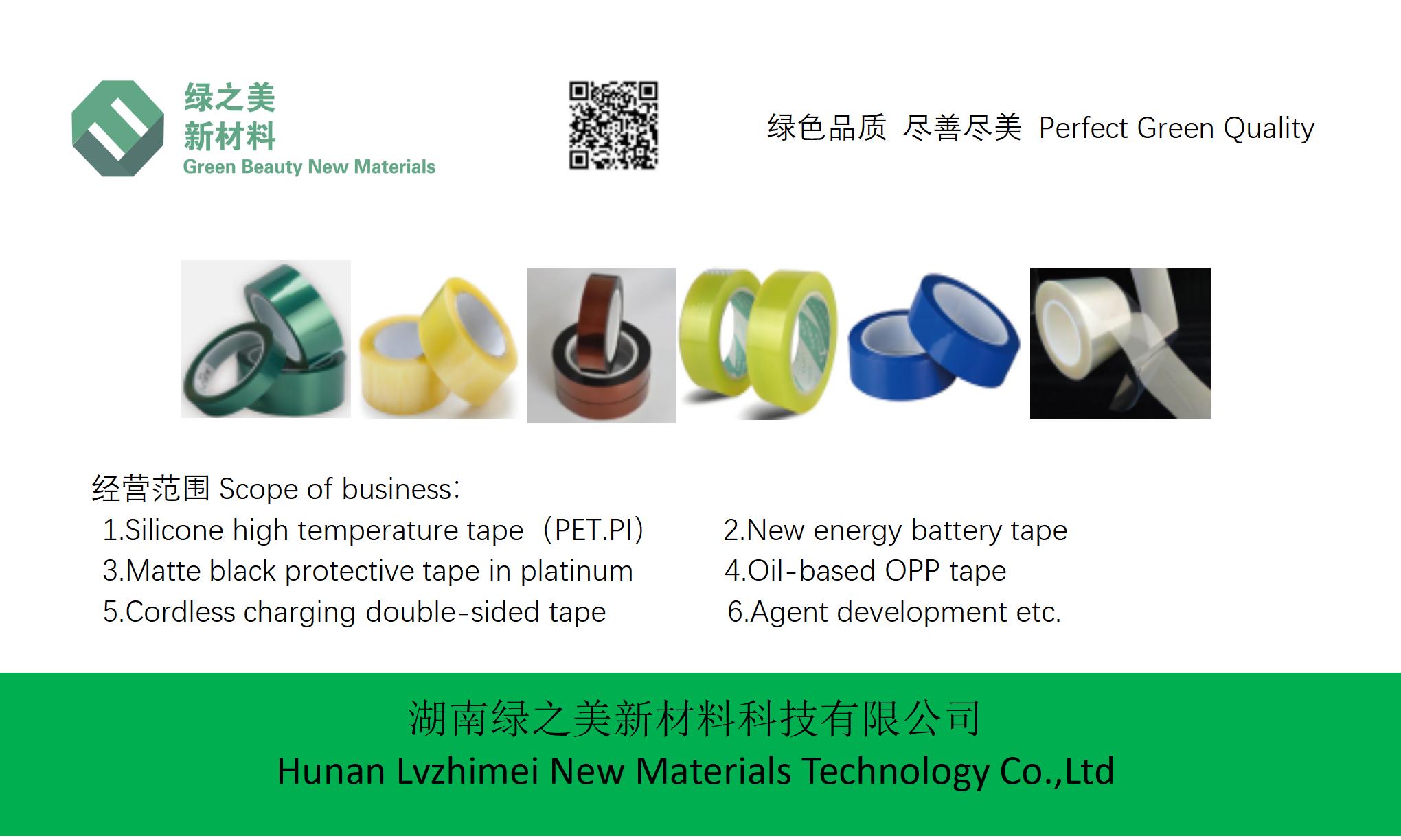
Adhesive PET material high temperature tape has long been a staple in consumer electronics manufacturing, prized for its cost-effectiveness, ease of application, and resistance to temperatures up to 200°C. However, as device performance requirements escalate—especially in areas like wireless charging and high-frequency electronics—PET tape’s inherent limitations can transform it from a convenient solution into a liability. This article delves into the critical scenarios where PET tape falls short, exploring its impact on energy efficiency, thermal stability, and long-term reliability.
The Double-Edged Sword: Advantages and Hidden Risks of PET TapePET tape’s widespread use in consumer electronics stems from its balanced combination of properties:
Key Advantages:
1.
Cost Efficiency: PET tape is significantly cheaper than high-performance alternatives like Kapton or PTFE.
2.
Versatility: It excels in applications like PCB solder mask protection, temporary component fixation, and basic thermal insulation.
3.
Ease of Handling: PET tape’s adhesive layer offers strong bonding without residue, simplifying assembly processes.
However, these advantages mask vulnerabilities that become glaring in demanding environments:
Technical Weaknesses:
1.
Dielectric Loss: PET’s high dissipation factor (Df ≈ 0.025) compared to Kapton’s Df ≈ 0.002 can severely degrade energy efficiency in wireless charging coils. Studies show PET tape increases energy loss by up to 12%, reducing charging speed and battery lifespan.
2.
Thermal Aging: While rated for 200°C, PET tape’s mechanical strength and adhesive stability decline rapidly beyond 150°C, risking delamination or adhesive migration.
3.
Chemical Resistance: Exposure to solvents, acids, or alkalis can weaken PET tape’s adhesion and insulation properties, posing risks in harsh manufacturing environments.
Critical应用场景:PET Tape’s Performance Bottlenecks1. Wireless Charging Coils: The Energy Efficiency ChallengeIn Qi-certified wireless chargers, PET tape’s high Df value creates two critical issues:
●
Excessive Heat Generation: Dielectric losses convert magnetic energy into heat, forcing devices to throttle charging power to prevent overheating.
●
Reduced Transmission Efficiency: A 12% energy drop directly impacts battery charge times and overall system efficacy.
Table 1: Comparative Dielectric Performance
Material | Dielectric Constant (εr) | Dissipation Factor (Df) |
PET Tape | 3.0-3.5 | 0.025 |
Kapton Tape | 3.2-3.4 | 0.002 |
Case Study: Wireless Phone Charger ComparisonWhen PET tape is used to insulate a 15W Qi coil vs. LVMEIKAPTON insulating electrical tape:
●
PET tape model: 82% energy transfer efficiency → 18% losses (12% attributed to Df).
●
LVMEIKAPTON tape model: 94% efficiency → 6% losses (2% Df-related).
The 12% efficiency gap directly translates to a 30-minute longer charging time for a 4000mAh battery.
2. SMT/Reflow Processes: Thermal Reliability QuandaryPET tape’s thermal degradation accelerates when exposed to prolonged high temperatures:
●
Adhesive Residue: Beyond 200°C, PET’s acrylic adhesive may carbonize, leaving sticky residues on components.
●
Film Shrinkage: PET can contract up to 5% at 250°C, causing tape to peel or wrinkle during soldering.
●
Insulation Breakdown: Weakened dielectric strength risks short circuits in densely packed circuits.
3. Long-Term Durability in Harsh EnvironmentsConsumer electronics often face:
●
Thermal cycling (e.g., automotive electronics)
●
Chemical exposure (e.g., sweat腐蚀 on wearables)
●
Mechanical stress (e.g., bending in flexible devices)
PET tape’s limited resistance to these factors can lead to:
●
Delamination from repeated heating/cooling cycles
●
Adhesive failure due to solvent attack
●
Cracking or tearing under mechanical strain
The LVMEIKAPTON Solution: Mitigating PET Tape LiabilitiesLVMEIKAPTON insulating electrical tape addresses PET’s weaknesses through advanced materials engineering:
Key Features:
1.
Ultra-Low Dielectric Loss: Kapton’s Df ≈ 0.002 minimizes energy wastage in high-frequency applications.
2.
Extended Temperature Range: Stable performance from -70°C to 260°C, ideal for reflow soldering and automotive environments.
3.
Enhanced Chemical Resistance: Resistant to acids, alkalis, oils, and solvents.
4.
Customization Options: Available in double-sided adhesive variants with peelable liners for complex assembly.
Table 2: PET vs. LVMEIKAPTON Tape Performance Comparison
Property | PET Tape | LVMEIKAPTON Tape |
Max Operating Temp. | 200°C (short-term) | 260°C (continuous) |
Dielectric Loss (Df) | 0.025 | 0.002 |
Adhesive Residue | Risk of carbonization | Clean removal |
Chemical Resistance | Moderate | Excellent |
Long-Term Stability | Degradation after 1 year | >5 years |
Real-World Application: LVMEIKAPTON in Premium Wireless ChargersA leading consumer electronics manufacturer replaced PET tape with LVMEIKAPTON tape in their 50W fast-charging docks. The switch resulted in:
●
15% energy efficiency improvement
●
Elimination of adhesive residue issues during reflow
●
100% pass rate in thermal cycling tests (-40°C to 85°C, 500 cycles)
Conclusion: Navigating PET Tape’s Risk-Performance BalancePET tape remains viable for low-power, non-critical applications. However, as consumer electronics evolve towards higher power densities, faster charging speeds, and extended lifespans, its liabilities become untenable. Design engineers must carefully assess application requirements:
●
If energy efficiency or thermal stability are paramount: Opt for LVMEIKAPTON tape or similar high-performance materials.
●
If cost constraints dominate: Implement PET tape with mitigations (e.g., thermal barriers, shorter duty cycles).
Ultimately, understanding PET tape’s boundaries ensures product reliability while balancing cost and performance objectives.
Hunan Lvzhimei New Material Technology Co., Ltd.
Quick Links
Product Categories
© 2024 Hunan Lvzhimei New Material Technology Co., Ltd.All Rights Reserved. Designed by Erge
0731 - 89717319
hnlzm@lvmeikapton.com
+86 13787123465
Room 502, Chuangye Building, No186, Guyuan Road, High-Tech District, Changsha, Hunan, China
CONTACT


