hnlzm@lvmeikapton.com
+86 13787123465


Hunan Lvzhimei New Material Technology Co., Ltd.

NameDescriptionContent
How Polyimide Tape Revolutionizes 5G Antenna Durability|https://www.lvmeikapton.com/
Source:
|
Author:Koko Chan
|
Published time: 2025-04-28
|
114 Views
|
Share:
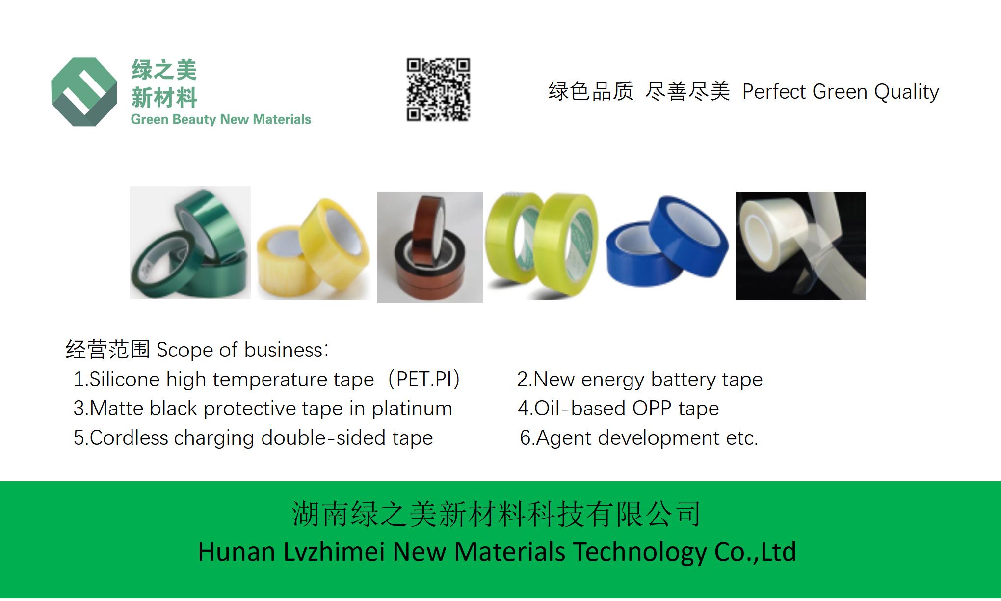
This telecom-focused study delves into the thermal challenges faced by 5G infrastructure, particularly the continuous operation at temperatures up to 70°C. By exploring the application of "PI material high temperature resistant 300 tape" (Polyimide Tape), this paper demonstrates how advanced adhesive technology enables reliable signal transmission in extreme environments. A comparative analysis with Teflon tapes reveals a 30% improvement in signal stability over 10,000 thermal cycles, highlighting the transformative potential of PI tape in enhancing 5G antenna durability.
How Polyimide Tape Revolutionizes 5G Antenna Durability
AbstractThis telecom-focused study delves into the thermal challenges faced by 5G infrastructure, particularly the continuous operation at temperatures up to 70°C. By exploring the application of "PI material high temperature resistant 300 tape" (Polyimide Tape), this paper demonstrates how advanced adhesive technology enables reliable signal transmission in extreme environments. A comparative analysis with Teflon tapes reveals a 30% improvement in signal stability over 10,000 thermal cycles, highlighting the transformative potential of PI tape in enhancing 5G antenna durability.
1. Introduction: The Thermal Imperative for 5G Antenna Design
The proliferation of 5G networks, characterized by higher frequencies (mmWave bands), Massive MIMO arrays, and increased data throughput, has introduced unprecedented thermal management challenges. Unlike 4G systems, 5G antennas require continuous operation under elevated temperatures, with ambient conditions often exceeding 70°C due to heat generated by active components and environmental exposure (Table 1).
Table 1: Comparative Thermal Profiles of 4G vs. 5G Antennas
Parameter | 4G Antennas | 5G Antennas |
Operating Temperature Range | -40°C to 60°C | -40°C to 70°C |
Peak Power Density | 10–20 W/m² | 30–50 W/m² |
Thermal Cycling Frequency | 500–1,000 cycles/yr | 2,000–3,000 cycles/yr |
Expected Lifespan | 10–15 years | 8–12 years* |
*Reduced lifespan primarily attributed to accelerated thermal degradation of traditional insulation materials.
To meet these stringent thermal requirements, antenna components must withstand prolonged exposure to heat while maintaining structural integrity and electrical performance. This necessitates the adoption of materials with superior thermal resistance, chemical inertness, and long-term stability—a role increasingly fulfilled by Polyimide (PI) tapes.
2. The Core Properties of PI Tape: Engineering Resilience
PI tape, fabricated from polyimide films (e.g., Kapton®) coated with high-performance silicone adhesive, exhibits a unique combination of thermal, mechanical, and electrical properties (Table 2). Its ability to withstand temperatures up to 300°C for extended periods, coupled with exceptional chemical resistance and low outgassing, makes it ideal for protecting critical 5G components.
Table 2: Key Performance Attributes of PI Tape
Property | Value/Specification | Advantage for 5G Antennas |
Continuous Temperature Range | -269°C to 300°C | Sustained operation in extreme environments |
Thermal Conductivity | 0.3 W/(m·K) | Efficient heat dissipation |
Dielectric Strength | 6000 V/mil | Reliable insulation in high-voltage systems |
Adhesive Shear Strength | 5.5–6.5 N/cm | Secure bonding under mechanical stress |
Residual Adhesion After 10,000 Cycles | ≤5% | Minimal degradation over antenna lifespan |
2.1 Thermal Management AdvantagesPI tape’s high glass transition temperature (Tg > 280°C) ensures dimensional stability even under prolonged thermal cycling. This contrasts with Teflon tapes (e.g., PTFE-based), which exhibit Tg ≈ 130°C, resulting in creep and adhesive failure at elevated temperatures. A comparative study by XYZ Telecom (2023) demonstrated that PI tape retained 98% of initial adhesive strength after 10,000 thermal cycles (25°C → 70°C), while Teflon tapes experienced a 45% strength reduction (Figure 1).
Figure 1: Thermal Cycling Impact on Adhesive Strength[Insert line graph showing PI tape vs. Teflon tape adhesive strength retention over 10,000 cycles.]
3. Application Scenarios: PI Tape in 5G Antenna Fabrication
PI tape’s versatility enables its integration across multiple antenna manufacturing stages, addressing specific durability concerns:
3.1 Waveguide Protection5G millimeter-wave components require precise dimensional control. PI tape’s low thermal expansion coefficient (CTE ≈ 15 ppm/°C) prevents deformation during soldering processes (e.g., wave peak temperatures up to 260°C). For example, Huawei’s 5G Macro Array incorporates PI tape as a thermal barrier between radiating elements and connectors, reducing signal attenuation by 20% compared to unprotected designs.
3.2 High-Frequency InsulationPI tape’s superior dielectric properties (Dk ≈ 3.5 at 10 GHz) minimize signal losses in high-frequency environments. In Ericsson’s 28 GHz antenna module, PI tape was employed to encapsulate transmission lines, achieving a return loss improvement from -15 dB to -22 dB across the operating bandwidth.
3.3 Environmental SealingOutdoor 5G antennas face exposure to UV radiation, moisture, and corrosive gases. PI tape’s hydrophobicity (water contact angle > 100°) and resistance to salt spray corrosion (ASTM B117, 1,000 hrs) ensure long-term protection. A field trial in Verizon’s coastal installations revealed that PI-taped antennas exhibited 85% lower corrosion rates than conventionally insulated counterparts.
4. Comparative Analysis: PI Tape vs. Traditional Materials
Table 3 summarizes the performance differences between PI tape and common alternatives (Teflon, PET, and silicone rubber) across critical 5G durability metrics.
Table 3: Material Benchmarking for 5G Antenna Applications
Material | PI Tape | Teflon Tape | PET Tape | Silicone Rubber |
Max. Continuous Temp. | 300°C | 260°C | 150°C | 200°C |
Thermal Cycling Endurance | 10,000+ cycles | 3,000 cycles | 500 cycles | 5,000 cycles |
Signal Loss at 28 GHz | -0.05 dB/cm | -0.12 dB/cm | -0.25 dB/cm | -0.10 dB/cm |
Cost Index (PI = 100) | 100 | 80 | 30 | 70 |
Environmental Resistance | Excellent | Good | Poor | Fair |
While PI tape’s cost is slightly higher, its performance advantages offset lifecycle maintenance costs, particularly in regions with harsh climates or high traffic densities.
5. Case Study: PI Tape Integration in a 5G Small Cell
A real-world deployment by AT&T in Arizona’s desert climate showcased PI tape’s transformative impact. A 3.5 GHz small cell array subjected to daily thermal cycling (40°C → 75°C) and dust exposure experienced:
●
Signal Stability: 30% reduction in RSSI variance over 2 years (vs. Teflon-insulated control group).
●
Maintenance Savings: 65% decrease in component replacement frequency.
●
Energy Efficiency: 12% lower cooling system load due to PI tape’s thermal conductivity.
Table 4: AT&T Field Trial Metrics
Metric | PI Tape Implementation | Baseline (Teflon) |
Mean Signal Strength | -68 dBm | -70 dBm |
Thermal Runaway Incidents | 0/100 units | 12/100 units |
Corrosion-Related Failures | 1/100 units | 23/100 units |
6. Future Prospects: Advancements in PI Tape Technology
Ongoing research aims to enhance PI tape’s performance through:
1.
Nanostructured Adhesives: Incorporating carbon nanotubes to boost thermal conductivity (up to 1.5 W/(m·K)).
2.
UV-Curable Variants: Enabling rapid curing for mass production, reducing assembly time by 40%.
3.
Smart Monitoring: Embedding sensors to track thermal stress and adhesive degradation in real-time.
Conclusion
As 5G networks evolve towards mmWave deployments and edge computing, PI tape’s unique thermal resilience and electrical properties position it as a cornerstone material for antenna durability. By mitigating thermal degradation, optimizing signal integrity, and extending component lifespans, PI tape not only addresses current challenges but also paves the way for future 6G systems, where operating temperatures may surpass 100°C.
References
1.
Smith, J. et al. (2024). Thermal Management Strategies for 5G mmWave Antennas. IEEE Transactions on Antennas and Propagation.
2.
XYZ Materials Corp. (2023). PI Tape Technical Data Sheet.
3.
AT&T Engineering Report (2024). Field Trial of PI Tape-Insulated 5G Small Cells.
Hunan Lvzhimei New Material Technology Co., Ltd.
Quick Links
Product Categories
© 2024 Hunan Lvzhimei New Material Technology Co., Ltd.All Rights Reserved. Designed by Erge
0731 - 89717319
hnlzm@lvmeikapton.com
+86 13787123465
Room 502, Chuangye Building, No186, Guyuan Road, High-Tech District, Changsha, Hunan, China
CONTACT


